Rosco’s LugNet Page
These pages are no longer updated. You can view my LEGO related pages here.
All images hosted by Brickshelf L.L.C. but who knows how long that will last.
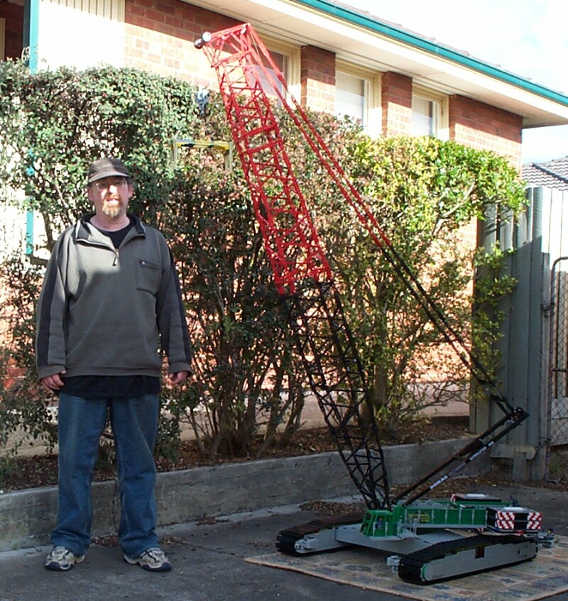
DEMAG CC-2800 crawler crane
Stage 1
The objective of Stage 1 is to build the carrier, and a short boom to test all the functionality.

Crawlers

Frame
| | The crawlers basically consist of 15 sets of wheels to take the load, and 2 sprockets - a driver and an idler. For the load bearing wheels I chose this combination as the best scale match. The sprockets are, as I said before, 24x43 wheels.
|
| | 
Outside view
| | But the crawlers are more than just wheel holders. They must spread the load from the superstructure as evenly as possible, carry the (very heavy) treads and drive them. They must also be removable to allow for transport.
|
| | 
Inside view
| | The load carriers are mounted on a thick beam running the length of the crawler. It is very rigid, thus helping to spread the load. The wheels are mounted 3 studs apart, and a “ridge” up the middle of the track fits between them, keeping it aligned. It also carries the mount points for the superstructure. The sprockets are attached to each end.
|
| | 
| | The sprockets each consist of 2 24x43 wheels. The driving sprocket is driven by 2 geared motors through a differential. One of the motors is geared down 3:1 before driving the differential, and can be reversed, thus giving 2 different speeds if required. The tracks have hinge tops set in it at regular intervals, that fit nicely in the tread of the 24x43 tyre, providing positive drive.
|
| | 
| | Update: OK, scrap the 2 speeds. I’ve found this reduces the driving power to the point where it’s only just able to move the crane with no boom and no load - it certainly wouldn’t be able to move with any kind of load. While that may not be possible anyway, due to the jerky movement, I think it’s a goal worth striving for, so the speed selection goes. Here is a pic of the crawler transmission. Each crawler is driven by 2 geared motors, through a 1:200 gear reduction.
|
| | 
| | The idle sprocket is mounted on a sliding frame, allowing the tracks to be tensioned. It has a full travel of around 3 studs, plenty to allow easy attachment/removal of the treads and enough tension to work correctly.
|
Tracks

| | Well obviously for such a large model, standard LEGO tread links were not an option. Given the dimensions of the tread shoes as about 14x3 studs, the only option was to “roll my own”. Each shoe is made of plates, and they are held together with 3 sets of hinge plates. Each also has an alignment plate in the centre and a hinge top to “mesh” with the driving sprocket.
|
| | 
| | Each track consists of 60 shoes. Because the hinge plates are offset 1 stud on each alternate shoe, they had to be in pairs, restricting me to an even number per crawler. I just experimented to get the best length that fitted nicely.
|
Superstructure base

| | This is carried between the 2 crawlers, and holds the slew ring. It also must be very strong and stiff, as it needs to spread the entire load to the crawlers, and provide a solid, level base for the slew ring.
It consists of technic beams sandwiched between plates, and mounted “studs out”, similar to those described by T.J. Avery here. They are very strong. It also has lateral beams of similar construction, and diagonal strengtheners as well.
|

| | 
| | A crawler is attached at each end, using 2 pins. Each pin consists of a column of 2x2 round bricks, with a #12 axle through the centre, and a 2x2x2 cone on the end. Two #10 axles are used to stop the crawlers rotating on these pins.
|
At the centre is a flat surface of plates, which hold the slew ring, which is a large wheel from the Hailfire Droid set. There are vertical beams through the centre of the ring, which are used to hold the superstructure against the slew ring.
Note that the real crane also has mount points for central ballast, attached to the base. It also has 2 arms with jacks on each side, which are used during setup to lift the base while the crawlers are attached. I have chosen not to model these.
Slew ring

| | The slew ring consists of a large wheel from the Hailfire Droid set, containing 33 small Technic wheels. These run against the bottom of the superstructure, which is studs out, giving a nice smooth rotation.
There is no centre axle in the slew ring, it is kept centred by 4 wheels mounted axle vertically, and running inside the slew ring. The teeth on the inside of the slew ring are used to rotate it.
There is also a clutch mechanism to allow the superstructure to swing free, which is useful when setting up.
|
Superstructure
The superstructure is mounted, as mentioned above, studs out on the slew ring. Two long plate beams are integrated into the swivelling base, and run the entire length of the superstructure. Everything is attached to these.
Mounted on the superstructure are:
- 3 winches (2 hoist, 1 a-frame winch)
- Air compressor
- 5 Motors (3 for winches, 1 for slew, 1 for air compressor)
- A-frame
- Cabin
- Mount points for ballast
- Connection points for remote control (tethered)
- Electrical distribution panel
Winches

| | The winches are just 40 tooth technic gears with axles and bushes connecting them. They are driven by 16 tooth gears. Each motor is separated from it’s winch by a clutch mechanism, allowing the winch to spin freely or be locked in place.
Update: The A-frame winch now has 2 gears, rather than a lock. A lower gear was required for lifting booms, and I didn’t want to remove the high gear, as it is useful for setup.
The a-frame winch is split in half by a third 40 tooth gear.
|
| | 
| | On the real crane, the hoist cable is much too heavy to be handled by the riggers, so a running winch is provided, which is just a smaller winch wound with much lighter cable. This cable is light enough for the riggers to be able to handle, so it is run to the end of the boom and back, tied to the hoist cable, and then wound in, consequently running the hoist cable. On my crane, I decided not to provide this functionality for 2 reasons:
|
- It is not needed - I am more than strong enough to run the hoist cable; and
- it would unnecessarily add to the complexity, requiring another motor, and control mechanism.
So I have a running winch, but the cable is fixed to it, and it just rotates freely.
Air compressor

| | 
| | The air compressor is used for moving the driver’s cabin. It needs to be swung between transport position and working position, and also needs to be tilted while working. This is done with compressed air.
Because the amount of air need isn’t great, only 2 small pumps are used 180 degrees offset. A large pneumatic cylinder with rubber bands and electrical switch are used as a pressure switch.
|
A-frame

| | The a-frame is mounted permanently to the superstructure, and is used to raise the boom or derrick. It is normally raised by a hydraulic ram, but in this model it just wasn’t possible so I raise it by hand.
Once raised, it is controlled by the a-frame winch, which uses a double 11-part line. The pulleys are Technic wedge belt wheels with the centres bored out (thanks Bob!). The line is a single line, running through a sway bar at the centre to correct for uneven winding on the winch.
|
Cabin

| | The cabin is fairly simple, and is mounted on a swing arm to allow it to swing between transport and working positions. A single pneumatic cylinder is used to swing it. The swing arm is 4 studs wide, 2-4 bricks high, and 23 studs long, so it’s fairly solid, enabling it to carry the cabin with minimal bending or twisting.
Purists please skip this paragraph! In this pic you can also see a beam marked on the end with an “X”. I actually had to file the corner off this brick, to ensure that the pneumatic cylinder rod didn’t hit it.
|
| | 
| | The cabin is hinged on the swing arm, allowing it to tilt while working. Two cylinders are required to tilt it. Note that although it is all hosed up for double-action operation, I chose to make it single-acting only, and allow gravity to push it down. This reduced the number of pneumatic lines to the remote by 1. I also decided to put the swing switch on the superstructure, as it is only used when setting up. This allows me to get away with only 2 hoses to the remote for tilting. cool.
|
| | 
| | It also has many driver comforts including comfortable seat, adjustable console, and sliding door for access.
For the railings I used Evergreen 3.2mm tubing, painted with Tamiya dark grey (XF-24) Acrylic model paint.
|
Ballast

| | Main ballast is provided by a selection of “ballast bricks”. These rest on a “ballast plate” which is attached underneath the superstructure by 4 pins. The ballast plate also provides significant ballast, weighing in at 900g.
|
There are 3 different weights of ballast bricks, which must be used in pairs, one each side. They have colour-coded plates on top to identify them. The approximate weights are:
- 580g (Red)
- 380g (White)
- 300g (Dark grey)

| | The crane can use up to about 3kg of main ballast - 4 bricks per side. Generally I only use 3, one of each type. Because the slew ring is not as strong as the real crane, the ballast can only be added when there is a boom attached to balance it, and may need to have some ballast removed once the boom is lifted.
|
Remote control

| | Control is provided by a tethered remote. It has 9 functions; 8 electric and 1 pneumatic switch for cabin tilt.
|
Power for the remote can be provided by a battery, but I usually connect a train controller and use mains power.
Electric functions:
- Slew
- Luff
- Hoist 1
- Hoist 2
- Crawler left
- Crawler right
- Auxiliary 1
- Auxiliary 2
Slew, luff, hoist 1 & 2 are provided on 2 joysticks, crawler and auxiliary switches are behind them. The 8 wires are collected together into 2 groups of 4, which are easily attached & removed from matching connectors on the underside of the superstructure.
The 2 pneumatic hoses can be attached to 2 “tee” pieces mounted near the electrical connectors. There is a switch onboard to disconnect these from the pneumatic circuit so the compressor can be run without the remote connected.
Electrical distribution
Slew and crawler functions are permanently connected, but the other 5 electrical functions can be changed depending on configuration. There is also an on-board battery, which can provide power without requiring the remote to be connected.
So the distribution block provides 6 input connectors for the various functions, and 6 wires to the different motors. Four of these are permanently in the superstructure, those being:
- Air compressor
- A-frame winch
- Hoist winch 1
- Hoist winch 2
The other 2 run forward to the boom connection point and allow connection to the boom & derrick winches as required. Note that the CC-2800 has a winch on the main boom which is used for the luffing jib, and a winch on the derrick which is used to luff the main boom, depending on configuration.

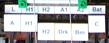
| | This picture shows a typical connection setup. The top row comes from the remote control, the bottom row are connectors for the various funtions. In this example, if we read left to right, we see the A-frame is connected to Luffing control, Hoist 1 is connected to Hoist 1 control, Hoist 2, Derrick and Boom are not connected, and the Compresser is connected to the on-board battery.
|
Boom

| | The boom is built in sections - I tried to make it as similar to the real crane as possible. Diagonal bracing on the sides is done using various combinations of Plates and Technic Plates. Technic Plates were used at the ends to allow braces to meet at adjacent studs/holes. The side bracing is attached by means of Technic 1/2 pins, top and bottom are just attached to studs.
The final length of the boom in stage 1 was 2.2 metres.
|
Stage 1 has 4 different boom sections:
- First section (contains auxiliary hoist winches)
- Wide sections (multiple)
- Narrowing section (reduced cross section of boom)
- Tip section (contains hoist pulleys)
First section

| | The first section is attached to the superstructure via 2 pins. The sides are parallel, but the side cross section goes from 4 studs at the base to 22 studs at the top, via 2 angled sections. The lengths and positions of the bracing were worked out by trial and error.
Note that the angle continues past the end vertical brace, so is slightly wider than 22 studs at the top, creating a “tight fit” on the first wide boom section. But it’s not enough to cause any problems.
It also carries 2 auxiliary winches, which are mounted near the top, where the rest of the boom attaches. One of these is just for display, the other is driven by a single motor, and can be connected to the hoist or luff controls at the electrical distribution panel.
|
Wide sections

| | These attach to the first section, and come in 2 different lengths, 4 and 7 (lengths measured by number of diagonal braces). As many are added as needed for a given configuration. each section carries the link rods needed to attach it to the a-frame or derrick, and also to attach the luffing jib arm if required.
|
Narrowing section

| | This section reduces the boom cross section from 22 studs to 20 studs on both sides. Again, the diagonal bracing was worked out by trial & error, and again the actual attachment points are slightly “out of line”, but this seems to work ok.
|
Tip section

| | This is the section that holds the hoist pulleys. It is fairly complex as it first reduces the cross section from 20 to 18, then widens vertically to the tip which holds the axles for the pulleys. The bracing required was a pig to work out, but it didn’t end up too bad.
There are 2 pulleys on the top axle, and 10 on the bottom, in 2 groups of 5. The top axle is also attached to the luffing links, and the bottom axle has a Model Team wheel on each end, for use when it is attached to a luffing jib.
|
Hook

| | The decision on hook design is basically a trade off (as with the rest of the crane) between looks and strength. I finally decided to go with looks, so it won’t break any lifting records. I may build a stronger hook later, we’ll see.
The hook has 8 pulleys, so could theoretically be configured with up to 17 part line, but the crane wouldn’t be strong enough to lift any weight which required that many lines anyway. And I probably wouldn’t be patient enough to wait for it to go up & down so slowly...
|
Weight
Here are the approximate weights of each of the parts:
| | Part
| | Weight (kg)
|
| |
| | Carrier
| | 4.5
|
| |
| | Crawler (x2)
| | 2.85
|
| |
| | Ballast
| | 3.35
|
| |
| | Boom (2.2m)
| | 1.6
|
| |
| | Parts for rigging
| | 0.1
|
| |
| | Remote control
| | 0.3
|
| |
| | Total
| | 15.55
|
Video
Here are links to 2 time-lapse style videos. The first is of the setup process, the second a small lift showing all functions, including traversing with the crawlers. If you really want the full video, including audio, email me. But I warn you it is over 100MB! Update: I’ve since found my ISP doesn’t like me trying to send 100MB emails, so if you want the video, I’ll have to send you a CD.
|
 |
Site last modified November 4, 2004 Home
|
