|
Ari Holopainen / epicyclic3 | |
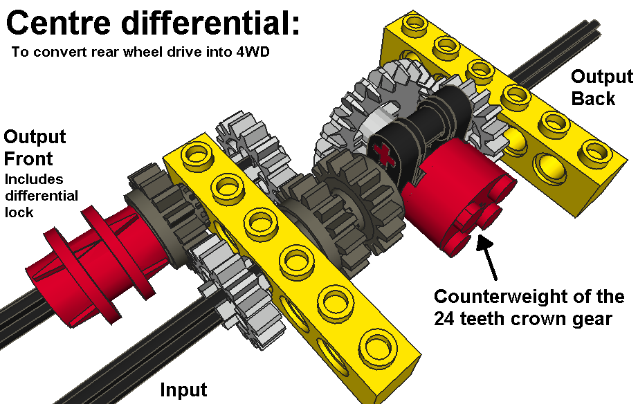
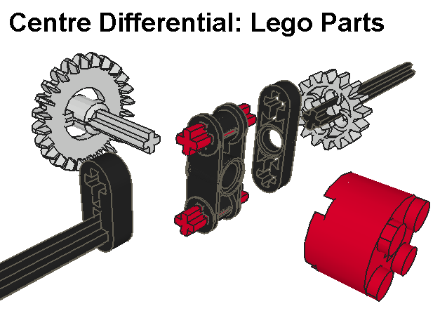
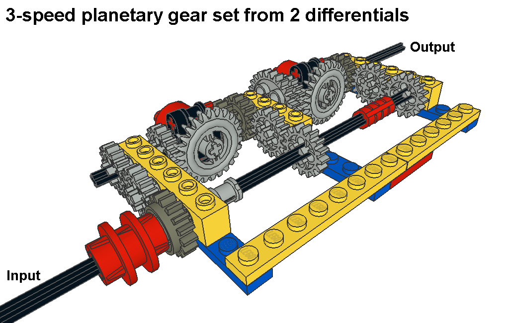
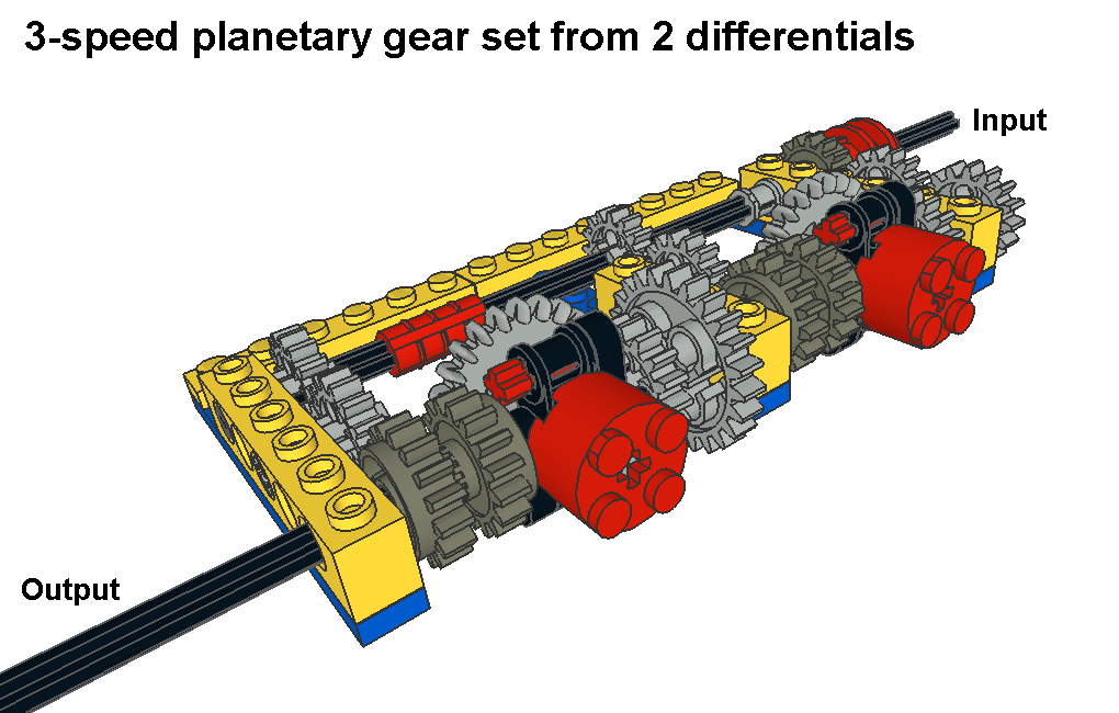
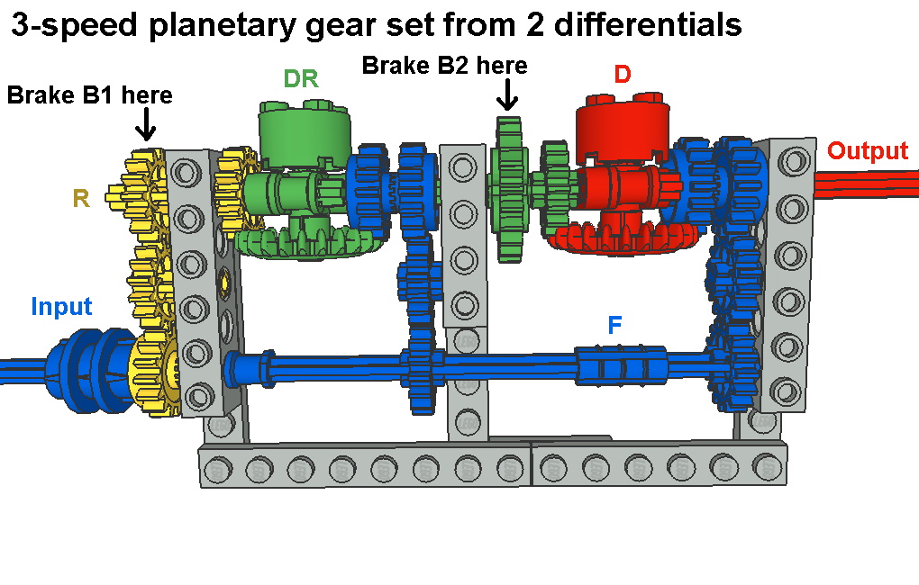
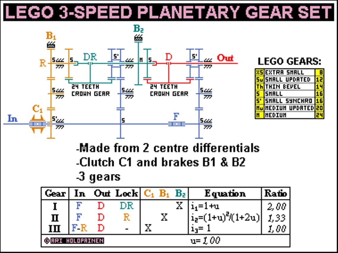
| E. 3-speed Planetary Gear Set From Two Differentials: E.1. Version I, centre differentials
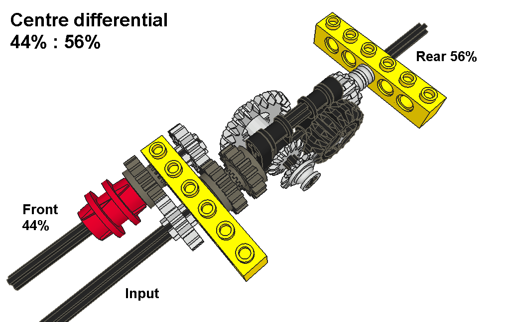
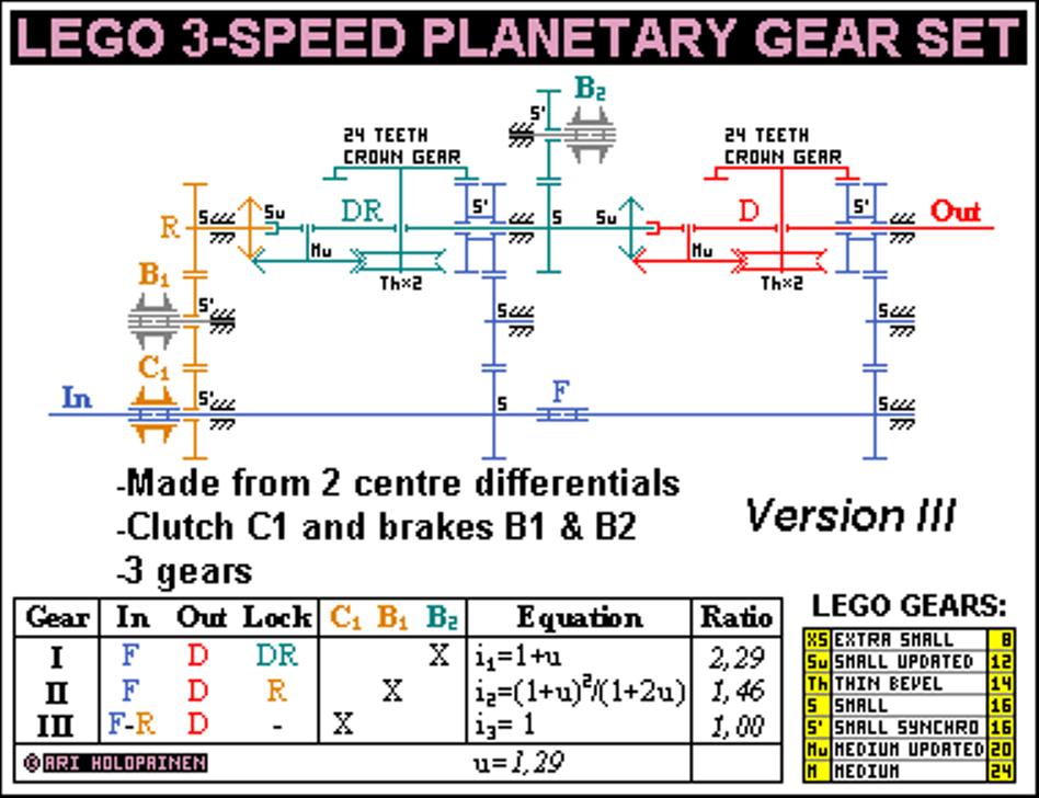
Here is 3-speed planetary gear set which is made from 2 centre differentials. You can think differential (50%-50% torque allocation) as basic planetary gear with basic ratio u=1,00. I have named parts as they are used in differential use so they sound a little bit odd for planetary gear set. 4 parts are: compound front outputs 1 & 2 (named as F) as input of gear set, single rear output 1 (R), compound differential housing 1 & rear output 2 (DR) and single differential housing 2 (D) as output of gear set. This equals to planetary gear set made from 2 basic planetary gears with compound sun gears and compound annulus & planet carrier, while sun gears are input and single planet carrier output.
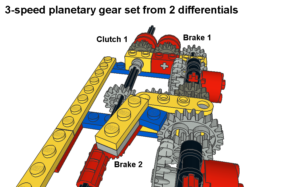
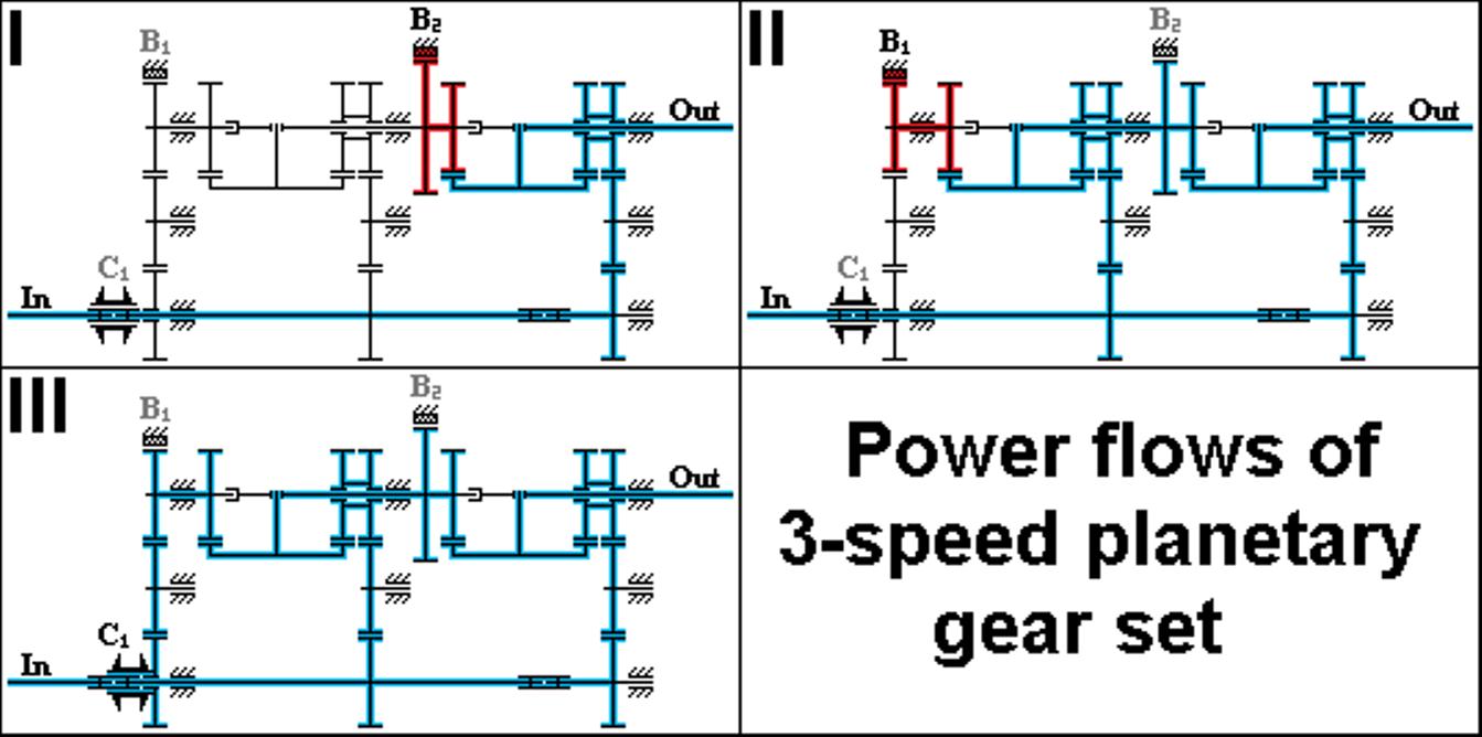
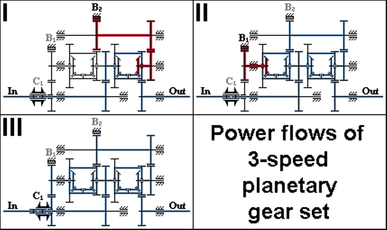
This planetary gear set has clutch C1 and brakes B1 & B2. Brakes are not modelled in all pictures or so check Gear set brakes for an example of two kind of brakes. Gear set parts or Schematics shows alternative positions for brakes. While F is always input you need to activate only 1 element of brakes or clutch to get a gear. When you lock one output of differential, use other output as input and take power out from differential housing you get ratio 2,00. It’s opposite situation of stuck car with only 1 spinning wheel, in that case stopped wheel causes other wheel to spin double speed. Using compound differentials gives perfect ratio (1,33) to 2nd gear so gear steps are progressive. Overall gear ratio (2,00) is too small but it’s near to 3-speed Simpson planetary gear set’s one. E.2. Version II, standard differentials
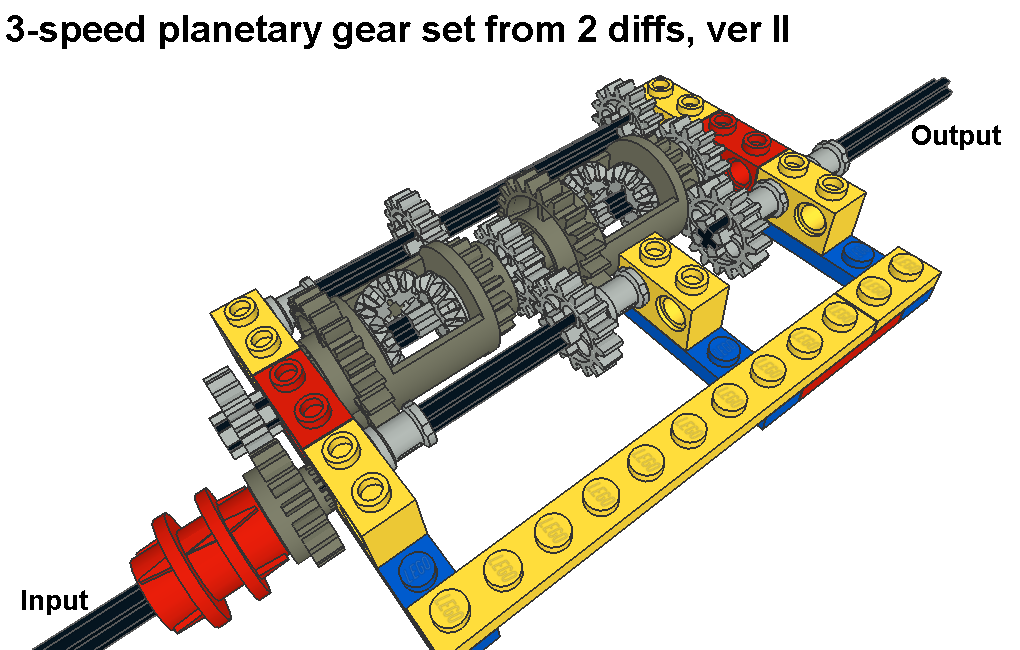
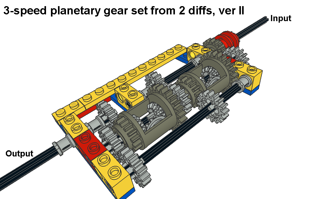
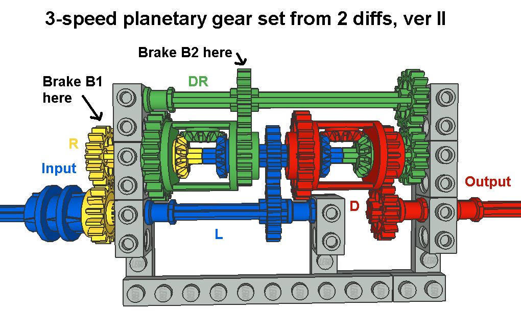
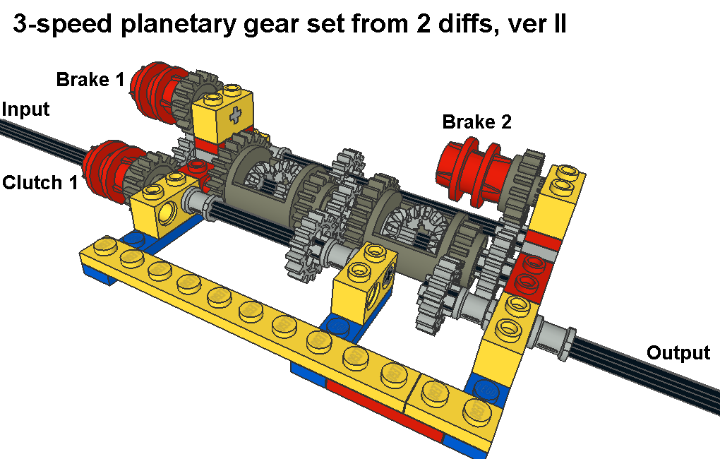
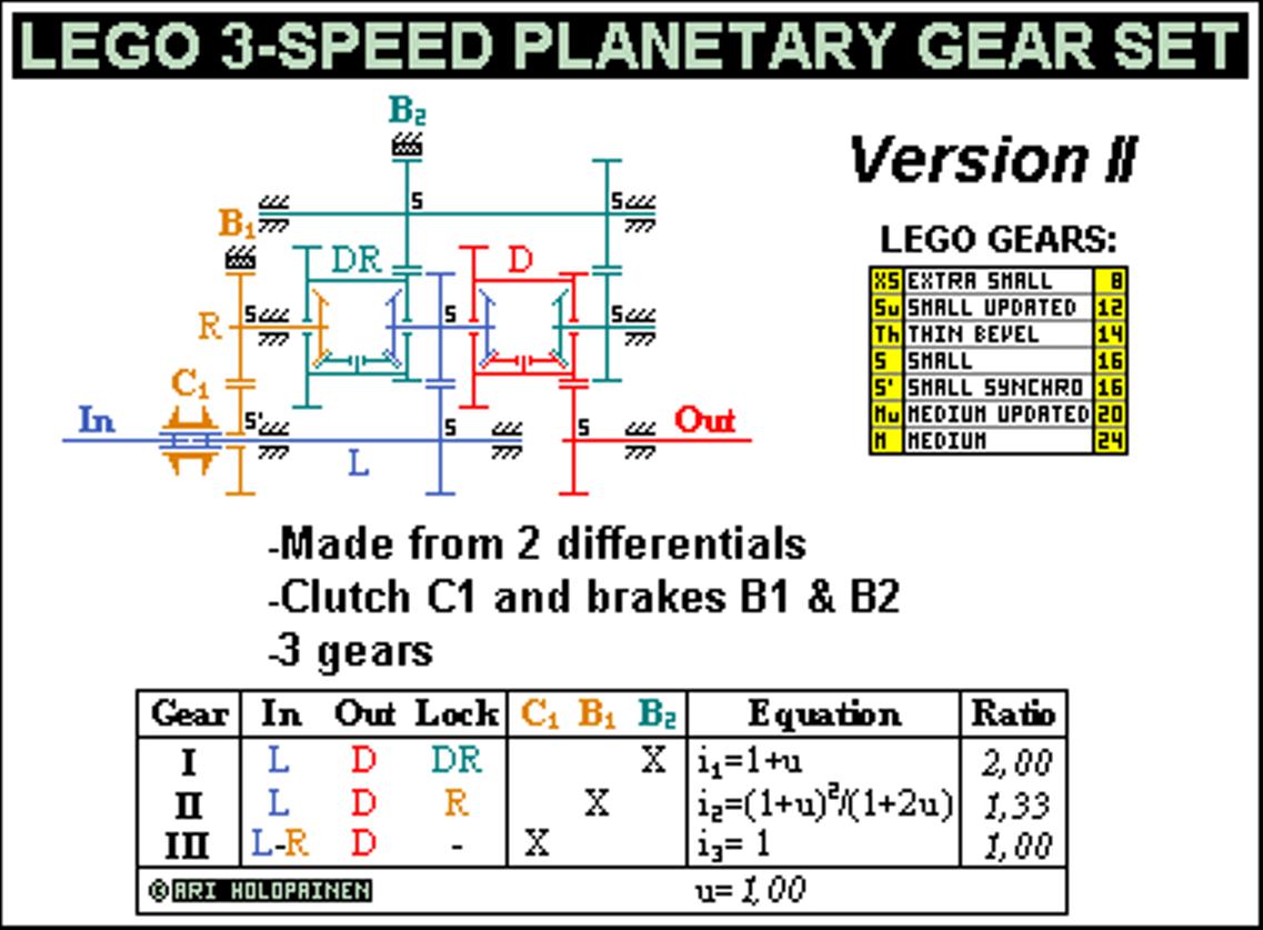
This version uses standard differentials. While basic ratio is same 1,00 also ratios and gear steps are same. Only names of gear set parts are different. This time 4 parts are: compound left axles 1 & 2 (named as L) as input, single right axle 1 (R), compound diff housing 1 & right axle 2 (DR) and finally single diff housing 2 (D) as output.
Also this version has clutch C1 and brakes B1 & B2. Brakes are not modelled in all pictures so check Gear set brakes to see one example about brakes and where to put them. Picture only shows locations so if you build this gear set brakes will need more support. Gear set parts or Schematics also shows where to put brakes, although brake 2 is in different location. E.3. Version III, 44%-56% centre differentials
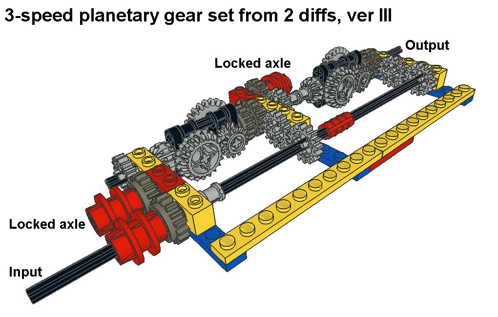
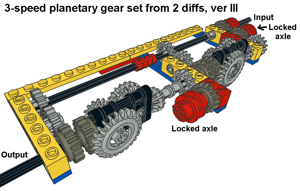
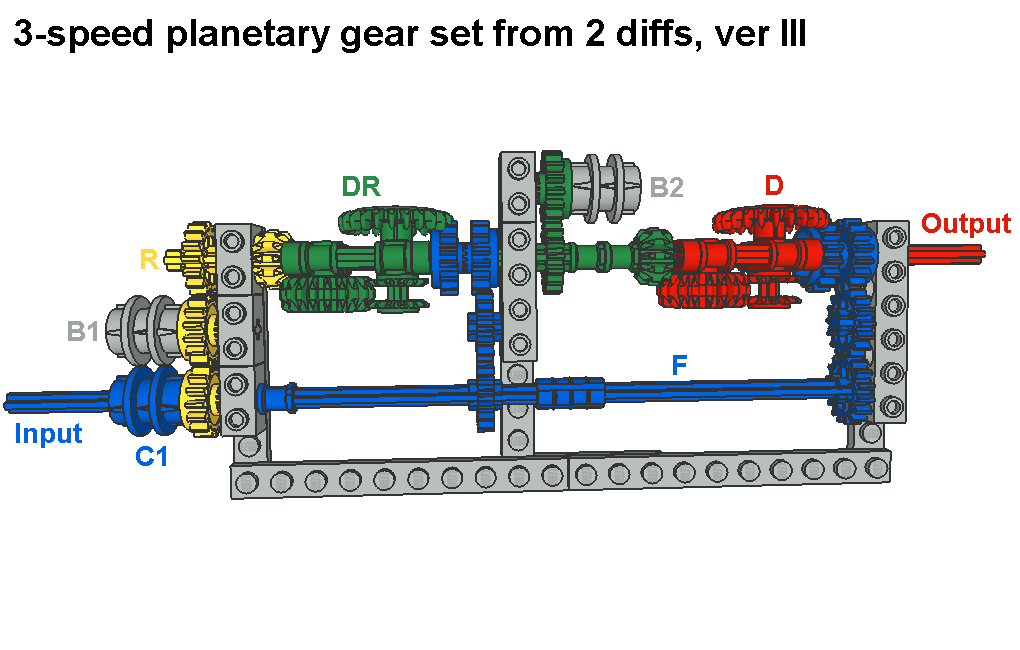
This version III has same centre differential parts as version I so check version I if you need more information. Basic ratio is now u=1,29 which gives larger overall gear ratio (2,29) but reduces gear step progression. Brakes are shown in all pictures and LDraw file. Power flow is not included because it’s same as in version I.
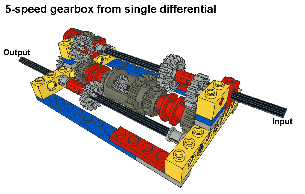
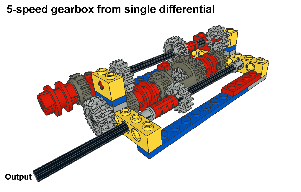
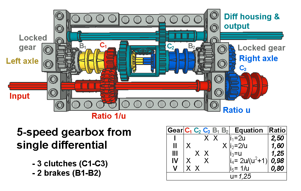
F. Gearboxes From Single Differential: F.1. 5-speed
Here is an idea how to get 5 gears from single differential. Differential’s left and right axle are alternately connected to input axle or diff housing or locked to ground. Diff housing works as output. There is an underdrive ratio u from input axle to right axle and counter ratio 1/u from input axle to left axle. You need 3 clutches (C1-C3) and 2 brakes (B1-B2) to operate this system and you have to connect 2 of them to get a gear. Check picture Schematics to see available ratios and how you get the gears.
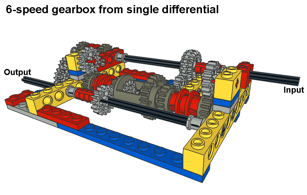
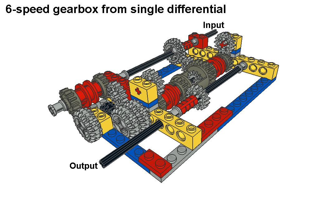
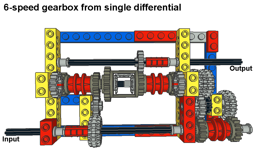
One interesting thing is that when you connect underdrive ratio u and overdrive ratio 1/u to right and left axle at the same time you could think you get a direct ratio. But it’s not direct, actually it’s most difficult ratio equation in this gearbox. F.2. 6-speed
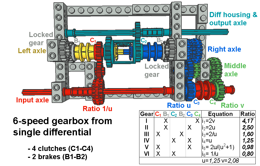
I found an easy way how to expand previous 5-speed gearbox to 6-speed version. You need 2 modifications: Put 16 teeth gears for idlers in gear pairs that are from input axle to left and right axle. Then put new 2 stage ratio v from input axle to right axle. It needs gear pairs S’(16C)-Mu(20) and Su(12)-Mu(20) to get ratio 2,08. This ratio v is used for new 1st gear, other gears are straight from 5-speed version. Now there are 2 clutches in input axle (C3 & C4) so gearbox has altogether 4 clutches and 2 brakes. Check Schematics to see how to get the gears.
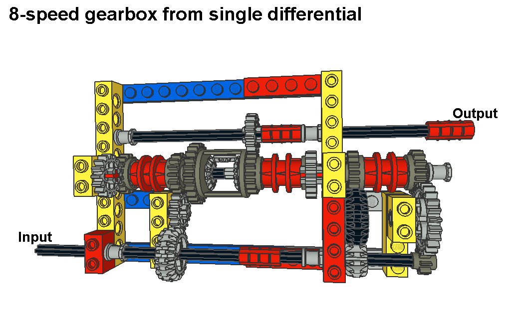
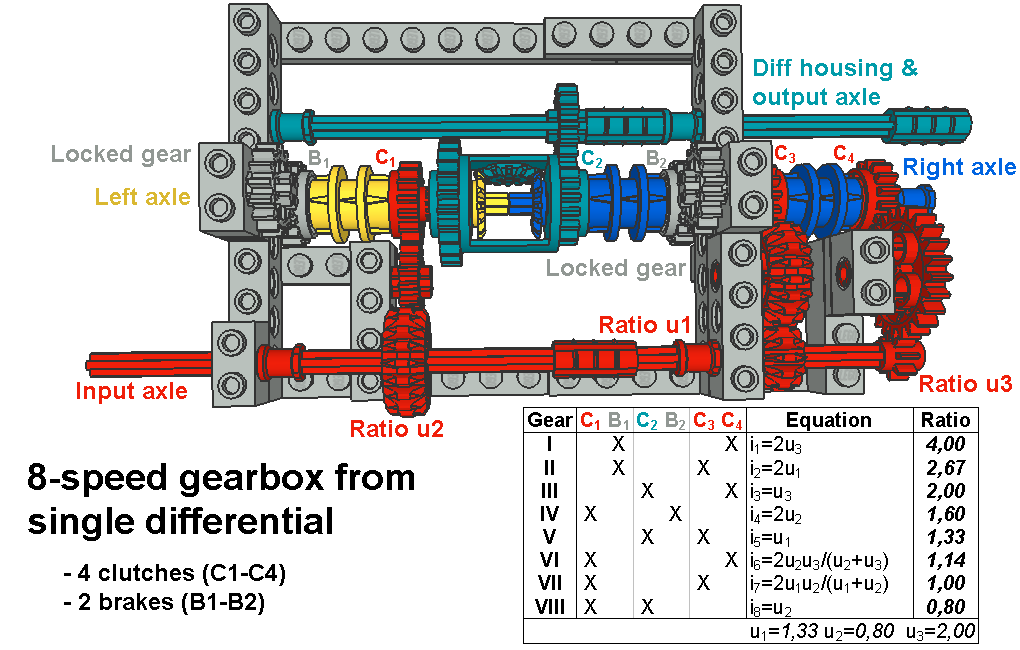
Overall gear ratio 5,21 is normal for 6-speed gearbox and gear steps are mainly progressive. So you can replace normal 6-speed gearbox with this differential gearbox although this version is more difficult to use. F.3. 8-speed
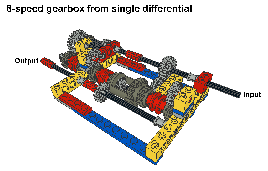
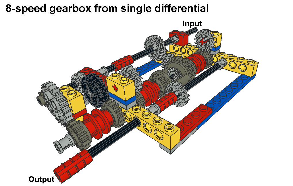
When you use 3 different ratios from input axle to left axle (ratio u2) and right axle (ratios u1 & u3) maximum number of gears is 8 for single differential gearbox. But I had to test different ratio combinations to get suitable ratios and gear steps. Gear steps and overall gear ratio (5,00) in this version are quite small so this is pure close ratio gearbox. Gear steps are also progressive except gear step 7-8.
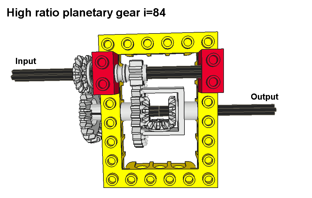
Like other planetary gear sets this gearbox is more difficult to use than normal manual gearbox with H shift pattern. If you manage to develop simple sequential shifting system for this gearbox, let me now about it. :-) G. High Ratio Planetary Gears: G.1. Version I, i=84,00, (with double i=7056,00)
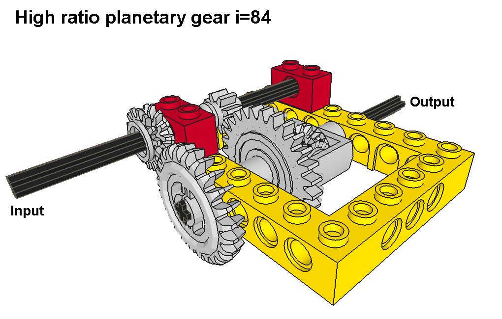
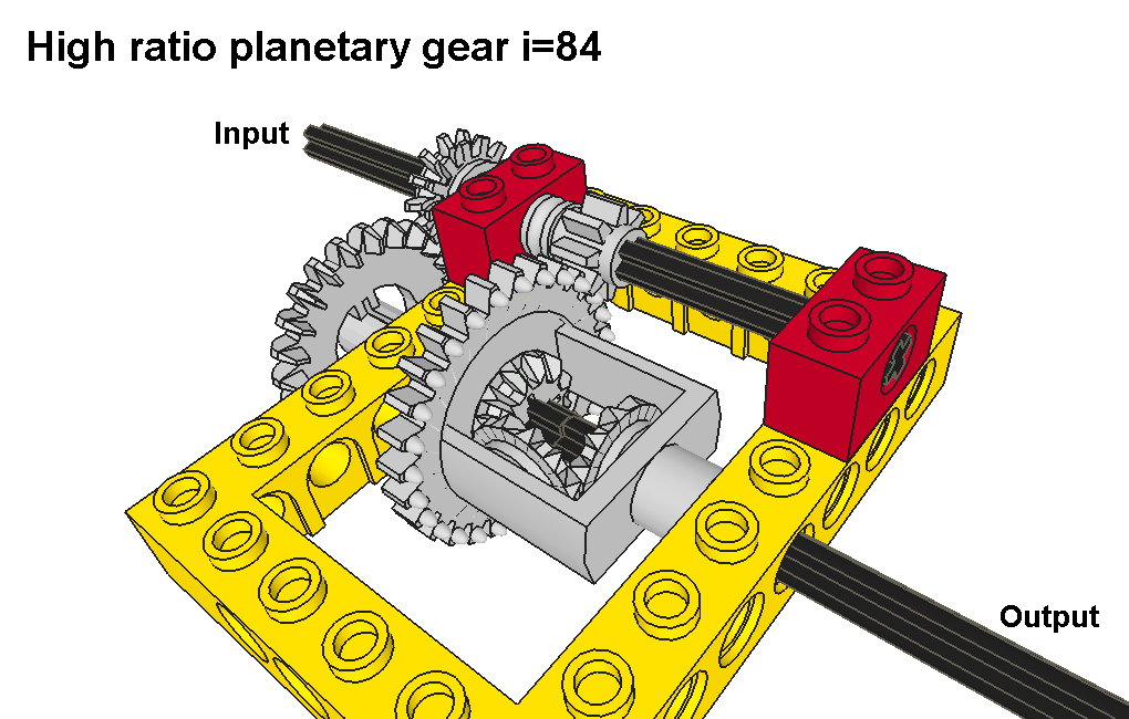
This is a single speed planetary gear which has as high ratio as 84,00. It’s done by old differential, but differentials are special purpose planetary gears. While there are normal gear pairs in this transmission, input and output axles should rotate in different directions. But they rotate in same direction so ratio is actually -84,00.
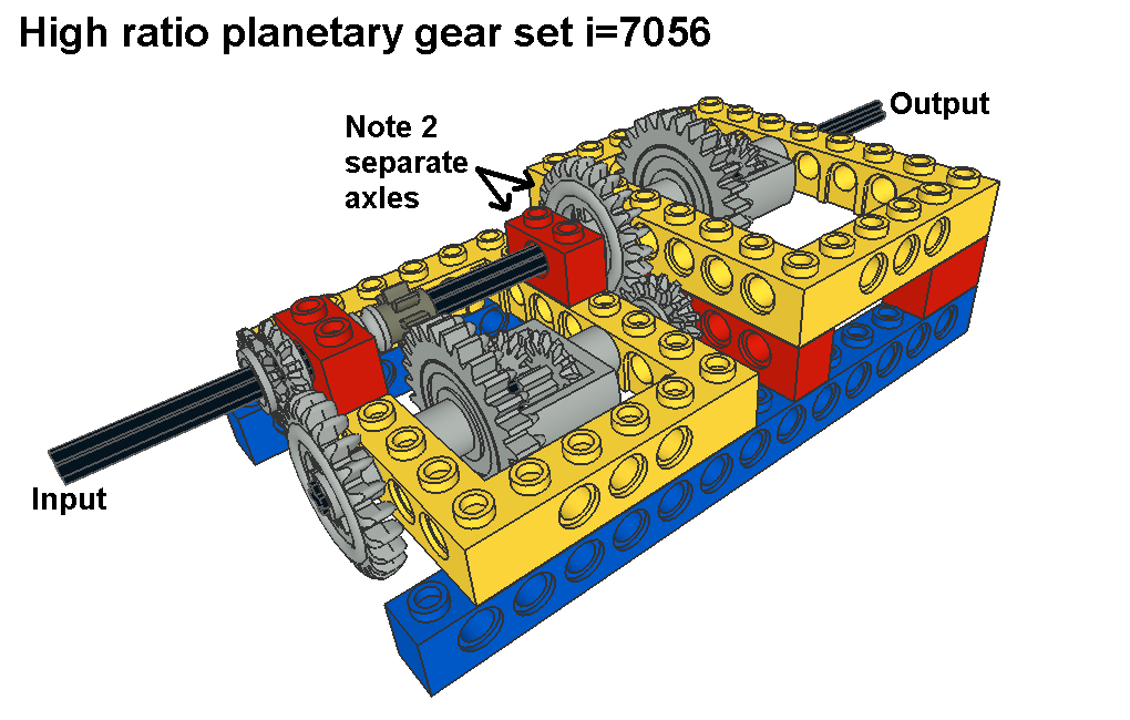
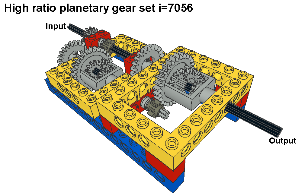
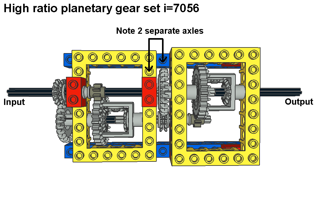
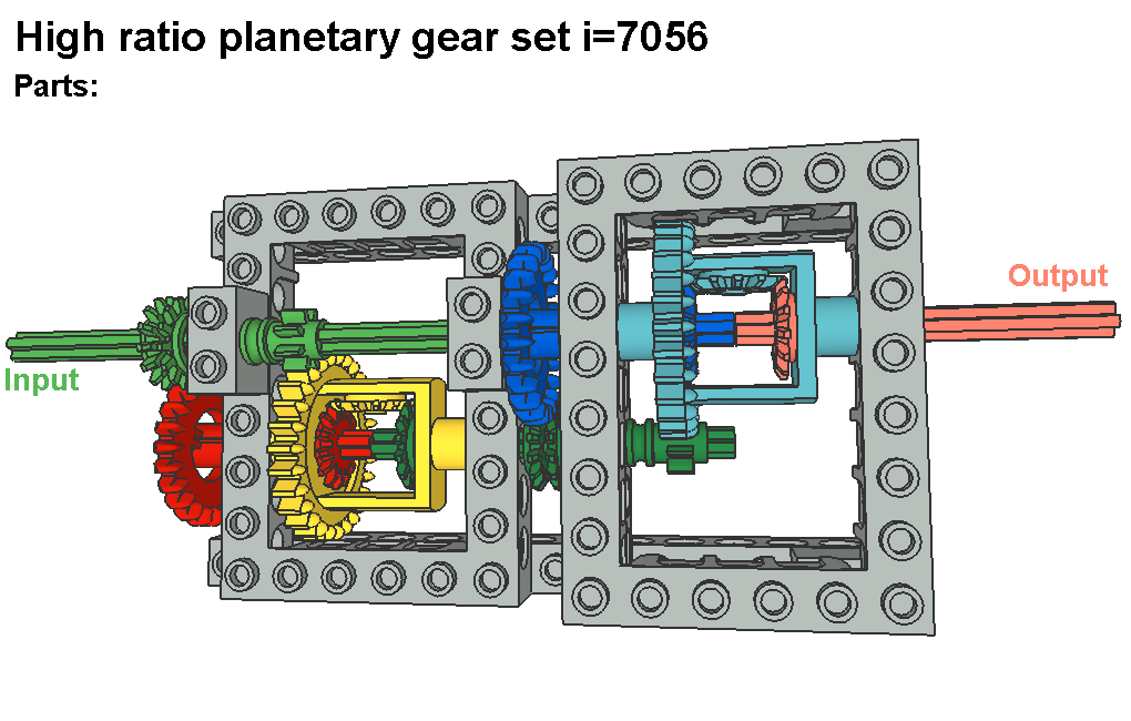
High ratio means also that gearbox’s efficiency is very bad, so this gearbox is not useful for vehicle use. With 4 XS(8)-M(24) gear pairs you get ratio 81,00 and it works much better than this planetary gear. And how do you calculate the ratio? With differential works equation N(diff)=[N(left)+N(right)]/2 in which N means part’s rotating speed. So output speed N(right)=2xN(diff)-N(left). Differential housing has speed reduction to N(diff)=8/28=2/7 and left axle N(left)=14/24=7/12. So we get N(right)=2x2/7-7/12=-1/84. If rotation speed of left axle is double compared to speed of differential housing, right axle doesn’t rotate at all. Now the ratios are close to this situation, so right axle barely rotates. But like in backgammon, “Let’s double, shall we?” So here is also double version in which high ratio planetary gear is used twice giving extremely high ratio 7056,00. This means that even fast 4500 r/min lego motor needs over minute to rotate output 1 round.
Note that this double version is coaxial structure so there are three separate axles in input/output line. Second 24 teeth crown gear is not in input axle but in left axle of second differential. Check picture Top view parts. G.2. Version II, i=64,00
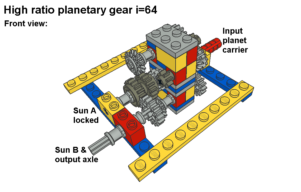
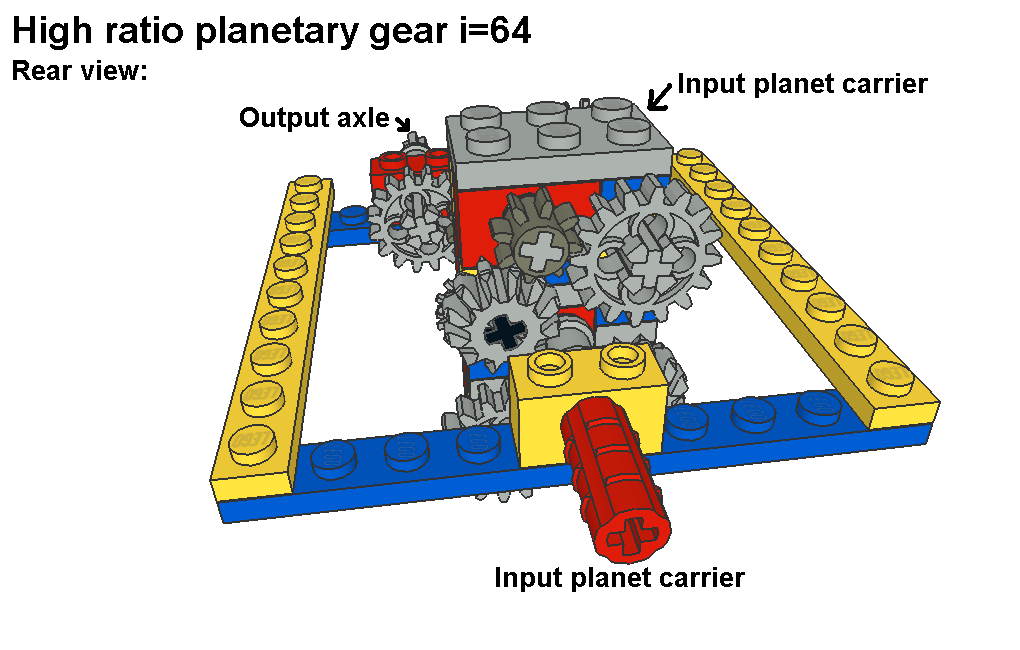
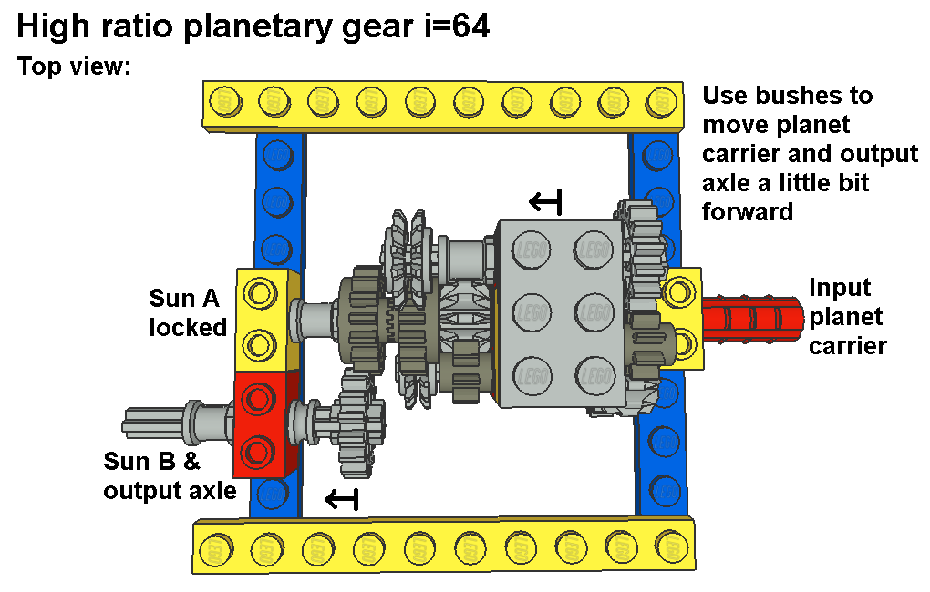
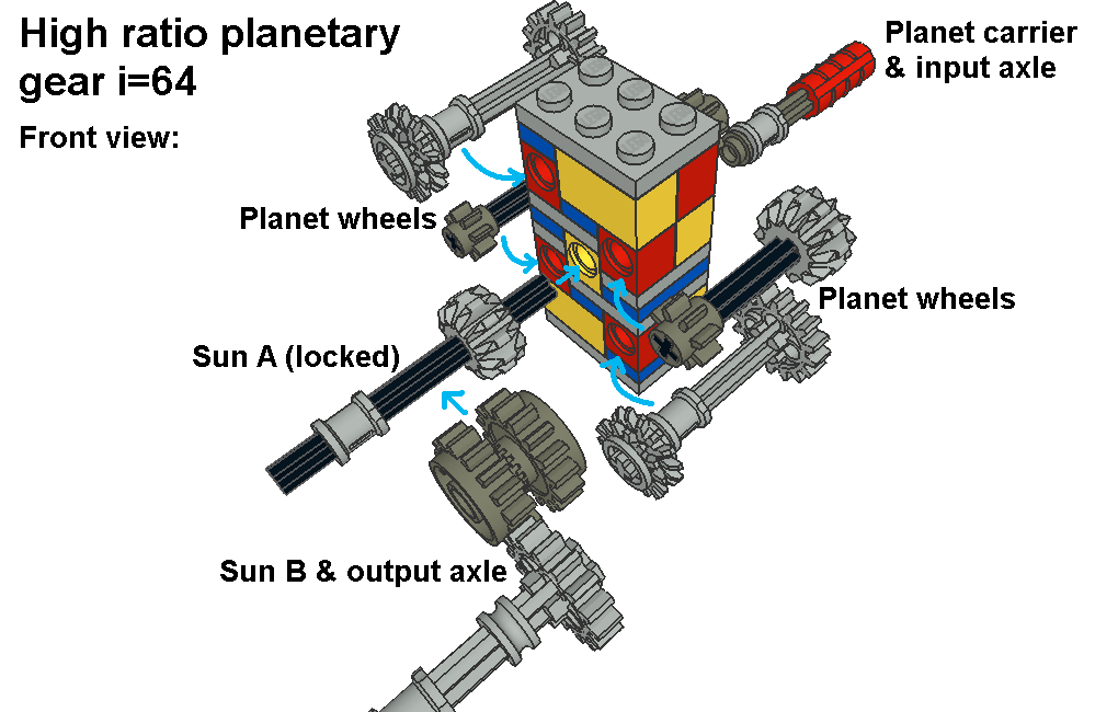
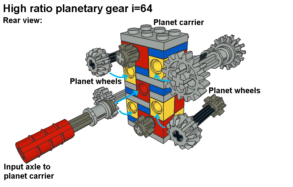
This high ratio planetary gear has same principle as my planetary gear version II although this planetary gear has more gear pairs in power flow. Essential is that number of stages is even number (2 in planetary gear ver II and now 4). To get high ratio you need two things: basic ratio u is near to 1 and planet carrier is input while sun gears A and B are locked and output parts. Now basic ratio u=8/12x16/12x16/14=64/63=1,016 and planet carrier is input, sun gear B output and sun gear A locked. So ratio i=u/(u-1)=(64/63)/(64/63-1)=64 in sun gear B. Note that output axle’s direction is reversed (i=-64) due to normal gear pair.
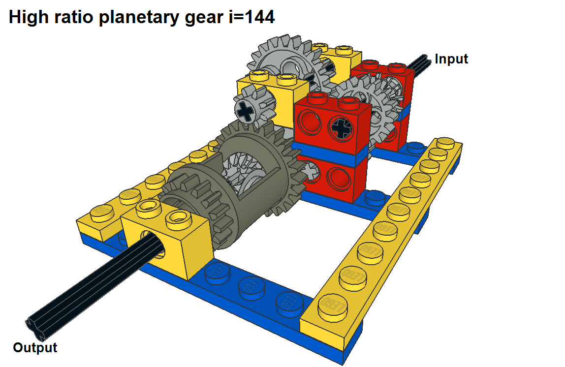
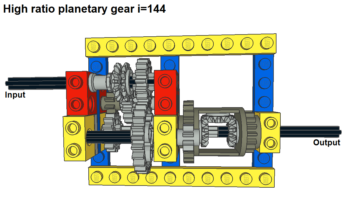
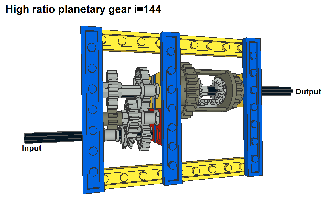
You have to remember that efficiency is not good in high ratio planetary gears so this planetary gear doesn’t suit to lego vehicles. For example 3 stage spur gear gearbox that uses gear pairs XS(8)-M(24) and two times XS(8)-L(40) gives better efficiency and higher ratio (75,00). If you want reverse ratio from this planetary gear you can simply swap sun gear A to output and sun gear B to locked part. Then ratio i=1/(1-u)=1/(1-64/63)=-63. Building tip: Planet wheels have possible collision problems with frame and output axle so you need some fine tuning. Use bushes to move planet carrier a little bit to output axle’s direction, sun gear B (16 teeth clutch gears together) allows that. Then move also output axle away from planet carrier, output axle has half bush is for that. G.3. Version III, i=144,00, (with double i=20736,00)
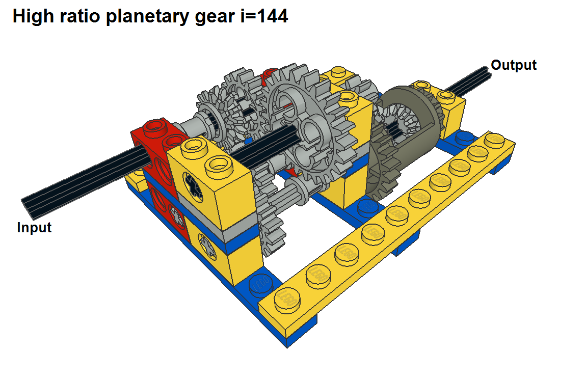
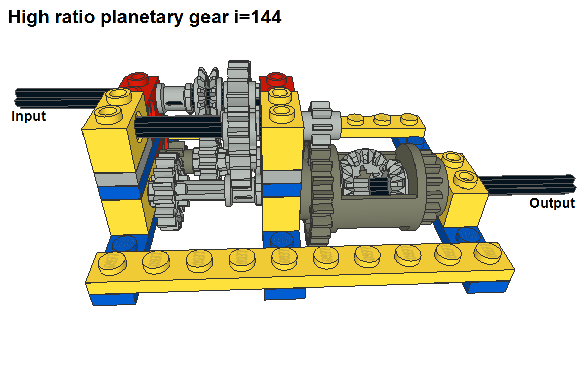
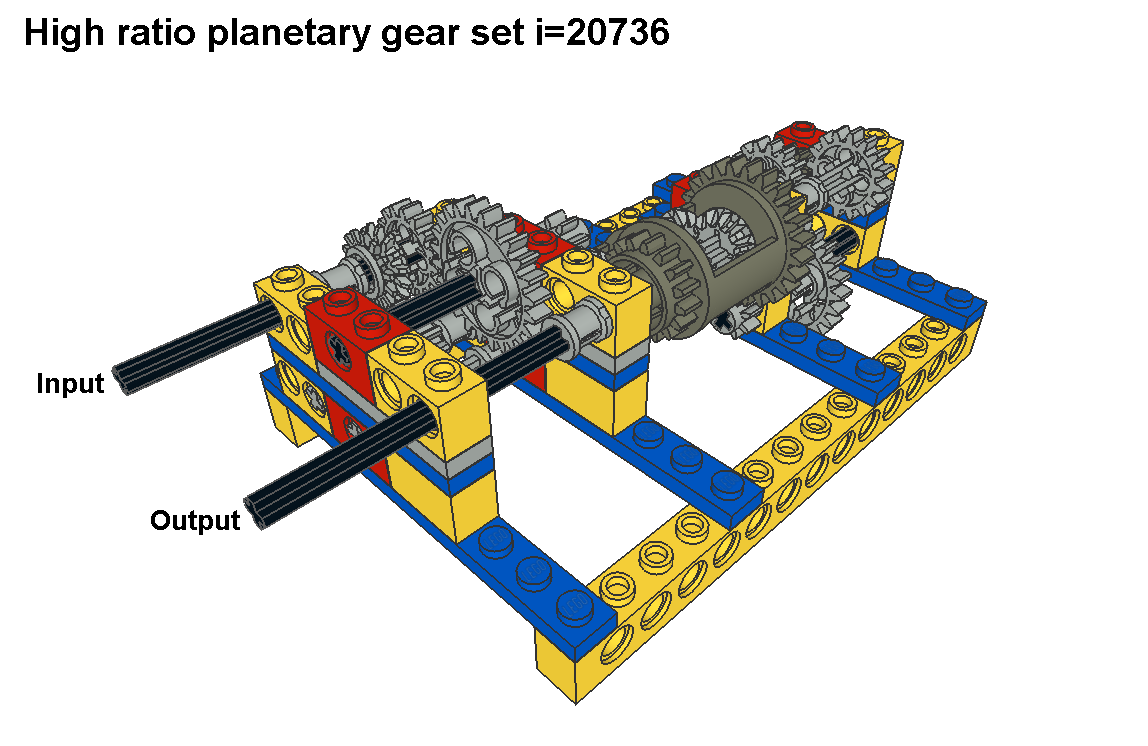
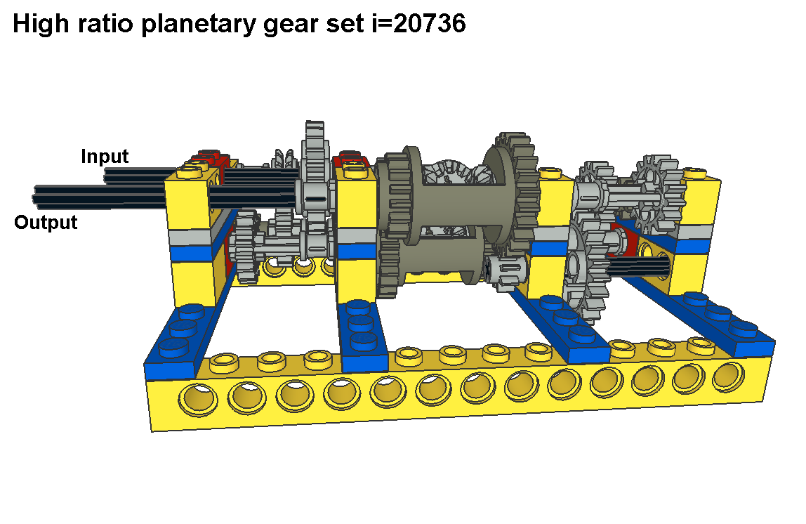
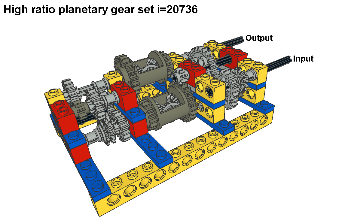
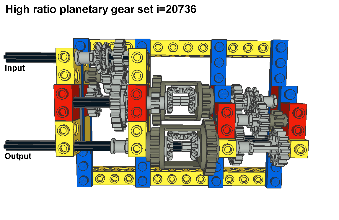
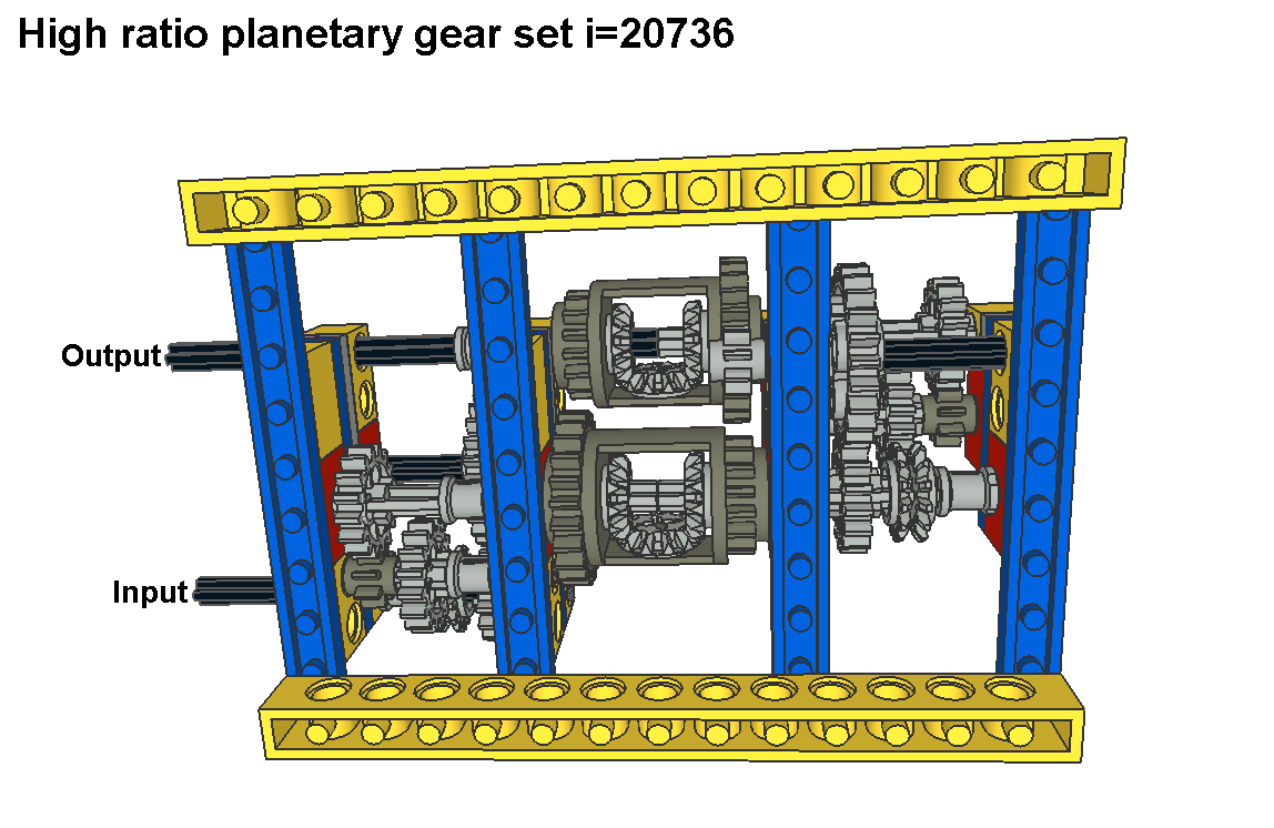
Here is another high ratio planetary gear that uses differential. This time ratio is as high as 144,00. Again ratio calculations need equation N(diff)=[N(left)+N(right)]/2 in which N is part’s rotating speed. So we get for output speed N(right)=2xN(diff)-N(left). Input speed to differential housing is N(diff)=16/24x8/24=2/9 and to left axle N(left)=14/16x8/16=7/16. This gives output speed N(right)=2x2/9-7/16=1/144. Although this version III is more complicated than version I you can still put two of these version III:s together. This double structure gives extreme ratio 20736,00 which means that fast 4500 r/min lego motor needs over four minutes to rotate output one round. H. Freewheel Clutch:
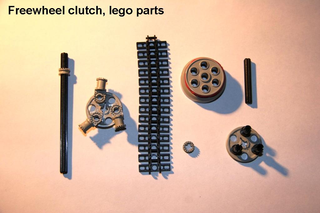
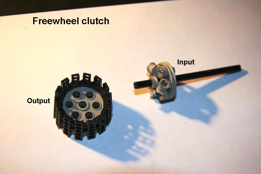
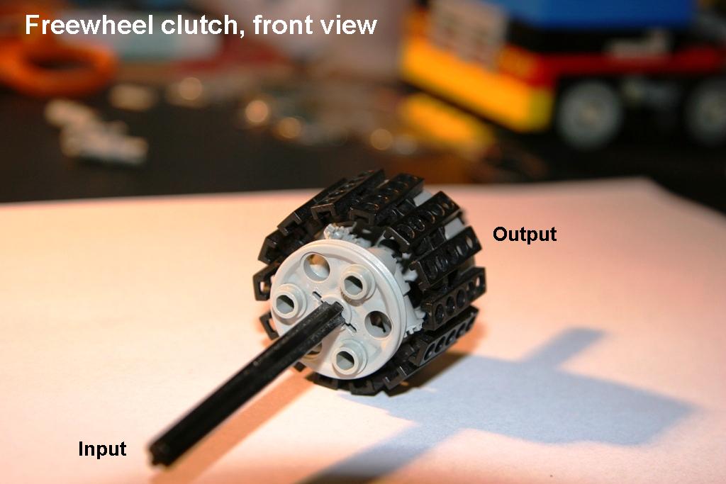
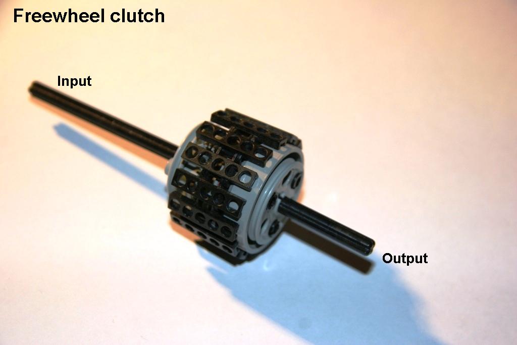
Actually freewheel clutch is not a planetary gear, but they use freewheel clutches in planetary gear sets, that’s why this is here. Freewheel clutches are used to disable engine braking in lower gears for smoother driving behavior and to simplify gear connecting. This one is from axle to axle freewheel clutch. Earlier in Torsen-Matic I have used from annulus to ground freewheel clutches.
Easiest way to understand how freewheel clutch works is to think multi-speed bicycle. While moving in forward pedalling locks the freewheel clutch and torque is transmitted. When you stop pedalling rear wheel keeps rotating free while freewheel clutch opens. So in locking direction torque is transmitted through freewheel clutch but only if output doesn’t rotate faster than input. Output can’t rotate input. When you try to reverse bicycle pedals rotate free and no torque goes through. But if you move bicycle rearward freewheel locks and rear wheel rotates pedals. So in freewheel direction no input’s torque goes through the freewheel clutch, but output rotates input if input doesn’t rotate faster than output. In this lego version key parts are technic connector toggle joints. In freewheel direction they hit to chain treads in such angle that they bound back but in locking direction at least one of them grabs hold of chain tread and starts to rotate output with input.
|
|
Primary content in this document is © Ari Holopainen. All other text, images, or trademarks in this document are the intellectual property of their respective owners. |
| |
©2005 LUGNET. All rights reserved. - hosted by steinbruch.info GbR |


