Rosco’s LugNet Page
These pages are no longer updated. You can view my LEGO related pages here.
All images hosted by Brickshelf L.L.C. but who knows how long that will last.
Mobile crane
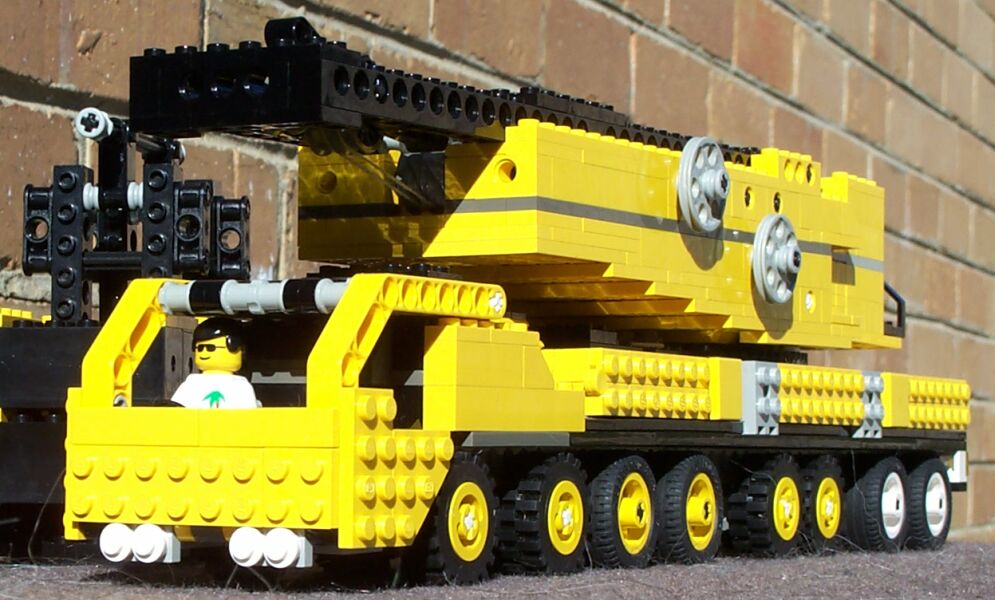
Since I saw Dennis Bosman’s model of the Liebherr LG 1550, I’ve wanted to build my own mobile crane. Since I’ve started building minifig-scale models lately, I decided to try & do one in that scale.
So after many hours work, here it is. It’s only based loosely on the LG 1550 - building vehicles at this scale always presents many challenges!

First, I had to fit all the functions into the chassis & super-structure. I needed 8 axles on the chassis, together with 4 extendable outriggers, and a turntable to hold the super-structure. I built a mock-up of the chassis & super-structure to try things & to work on getting the scale right.
The first challenge was to select wheels of a reasonable size; I’d decided to limit the chassis to 8 studs wide. First, I tried these, but they were too large. I also looked at these, but I didn’t have enough of them, and they were still slightly too large anyway. I finally settled on these, which was a little small, but I thought they looked the best. Later, I decided to use a combination of those and these, to get the 2 different wheel types.

| | So, now I had the wheels selected, I needed to look at outriggers. These needed to be extendable, and strong enough to provide some stability. Ideally they should be able to take the entire weight, but after much experimentation, I realised that getting them that strong while still being able to fold them into the chassis was going to be too hard, so I settled on a solution using click-hinges, and hinge plates to unfold & extend them. Unfortunately, this meant the chassis has to be lifted to unforld them, but I was still pretty happy with them.
|
| | 
| | I also wanted to design some travers to be as real-looking as I could. Using slope bricks & round bricks - I’m pretty happy with the result.
|
Now I had to look at attaching the super-structure. First, I started using the 4x4 turntable, but it just wasn’t stable enough - it allowed too much tilting in the super-structure, so I switched to the technic turntable. This required a re-design of the chassis (and the super-structure, which was also quite a way along by then).

| | 
| | Later, I also fitted a locking mechanism to stop it rotating during transport. It consists of a 1x6 hinge plate which slides; the end with 2 fingers locks with the teeth on the turntable. There’s a rubber band holding it in the “locked” position, and a lever releases it. In another happy accident, the lock lever can’t be operated until the outrigger obscuring it is moved, reminding the operator to shure up before operating the crane!
|

| | And, of course, during all this, I had to work on getting a reasonable looking cab, and engine.
|
Then came the super-structure. It had to contain a driver’s cab (with driving & transport positions, and tiltable), 4 winches, a-frame, mounting points for derrick & boom, and main ballast.

| | I started with the general shape. It needed to have the slope upwards on the bottom away from the turntable. I’m pretty happy with how it turned out.
|

| | 
| | 
| | The first challenge in the superstructure was the driver’s cab. This rotates using 2x2 turntables from the transport position towards the rear, to the working position at the side. After building it, I realised it was going to need something to hold it securely in either position. This is done with a sliding plate & rubber band. It also tilts using a 3L technic pin, but only while in the working position. The cab mount is actually my favourite part of the model!
|

| | Next, I had to fit 4 winches. I wanted to use hose reels for friction, similar to my crawler crane, but realised pretty early that the hose reels wouldn’t hold enough string for this crane. So the actual winches consist of 2 16 tooth gears on an 8L axle, separated by 2 studs. They are driven from below by another 16 tooth gear, on an axle which goes through a hose reel. This works really well, but forced me to make the super-structure a plate or two higher than I really wanted!
|
Then came the A-frame, which is permanently mounted on the super-structure. It originally had a 4 part line, but this proved insufficient, and I later increased it to 5.

| | The main ballast consists of 8 2x6x2 train weights (4 on each side), held by a frame which attaches to the super-structure. It also contains link points for the suspended ballast frame.
|
There is also a 6 cylinder engine in the super-structure.
After getting the chassis & super-structure how I wanted them, I needed to think about the actual boom construction. This is always one of the more difficult challenges faced in building LEGO cranes. It must be strong enough to support the weight, but light enough that not too much ballast is required. I realised early on that using technic beams was going to end up way too heavy, so I tried plates (similar to HoMa’s Gottwald crane), but that was going to be too heavy too, and I didn’t have enough 1xN plates to do it this way. So I decided on using 12L axles, held together in groups of 4 by 1x4 liftarms, with groups of 4 connected with axle connectors. This also allowed them to be modular, the modules connected with #2 connectors. But I couldn’t figure out a good way to add diagonal bracing, without a significant weight increase, so it doesn’t have any. This means twisting, and to a lesser extent bending, becomes an issue with long booms / jibs, but I can live with it.
I had to make a derrick, a boom and a jib. They all use the same construction technique; the derrick is 6 sections long, the boom is 10 sections, and the jib is 7 sections (each section being 1 group of 12L axles). Each also has a mounting section. Each has extra stuff attached to allow for running & connection of cables. The derrick & boom are about the length (scale-wise) of the maximums for the LG 1550, but the jib is only about half the maximum, because I ran out of 12L axles.
For describing crane configurations, Liebherr use the following table:
S
| | Main boom, heavy
|
| | L
| | Main boom, light (not used)
|
| | N
| | Luffing jib, light (not used)
|
| | W
| | Luffing jib, heavy
|
| | D
| | Derrick
|
| | B
| | Suspended ballast
|
To give you an idea of how it all fits together, I set it up in a SDWB configuration, and took some pictures:

| | 
| | 
| | 
| | 
| | 
| | 
|
| | First, the outriggers are unfolded, extended, and the travers & pads fitted. Make sure you’re on level ground!
| | Next, raise the A-frame. In real life, hydraulic rams are used to do this
| | Now the A-frame can be used to help lift the derrick into place
| | The derrick is mounted, and connected to the A-frame. The link for the suspended ballast is also attached
| | The derrick is raised halfway, and can now be used to help lift the main boom into place
| | The A-frame must be lowered, while keeping the cable to the boom tight - that’s all that’s stopping the derrick from falling!
| | The derrick is in it’s working position, with the suspended ballast link also in place. The jib can now be attached
|
| | 
| | 
| | 
| | 
| | 
| | 
| | 
|
| | Connect the jib, and lifting cable, which is run through the derrick for a good reason, explained later
| | Run the hook cable all the way out to the jib. Only use 2 part line, as the lift limit is fairly small anyway
| | Now raise the main boom. The suspended ballast is required while doing this. Now you can see why the cable is run through the derrick - so that the jib stays approximately level while raising the boom
| | Raise the jib to the required position
| | Slowly start the lift
| | And lift it as high as you need
| | The giant obviously needs a beam replaced...
|

| | All crane manufacturers supply tables of lifting capacities for the various lifting combinations. For the LG-1550, the maximum capacity is 550 tonnes, but this can only be achieved at 4.5m readius with a special boom head and another support base. In general configurations, the maximum capacity is 350 tonnes. I wanted to get close to that, which meant I’d have to lift about 1.6 kg. This proved impossible - the most I was able to lift (or prepared to try anyway) was about 820g (a stock-standard UCS TIE Interceptor™), at a radius of about 10cm. This is using an “S” configuration, which isn’t actually offered by Liebherr, only a combination “SL” is available.
|
| | 
| | As the radius increases, the capacity decreases. Here, I’ve extended the boom, and increased the radius to about 25cm, reducing the capacity considerably. I can now only lift an X-wing™.
|
| | 
| | At 40cm, the capacity has reduced such that I can now only lift a small “Island Hopper” plane.
|
| | 
| | In the “SD” configuration, at the maximum radius of about 80cm, I can only lift an “Island Racer” car.
|
I didn’t weight test the SDW or SDWB configurations, as by this time the wind has increased quite a bit, and even the real LG-1550 is not rated above 14m/s winds!
See other pictures here
|
 |
Site last modified November 4, 2004 Home
|
