Rosco’s LugNet Page
These pages are no longer updated. You can view my LEGO related pages here.
All images hosted by Brickshelf L.L.C. but who knows how long that will last.
Helicopter
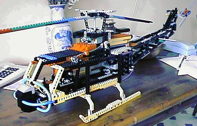
Well, I’ve built a couple of “standard” Lego helicopters in the past, but I needed a challenge, and I happened across some really neat web-pages that showed how the helicopter controls work.
And naturally I thought “it should be possible to do that with Lego!!”. So I started to ponder...

| | Tail Section
The tail rotor control seemed pretty basic - just adapt the 852 main rotor control. Problem was, the 852 used gravity to hold the rotor against the control, so I had to introduce a couple of rubber bands to solve this one. If you look closely in the picture below you can see I modified this slightly in the final version.
|
It was around this time I decided to model my creation after the Bell UH-1 (Huey). I’m not sure exactly why, but in hindsight, here are e few things which may have contributed:
- It’s very recognisable. Due to it’s extensive use in the Vietnam war, and the endless movies about it, I figure most people have seen one at some time or another.
- It’s one of the few with a two-blade main rotor. My design could conceivably be extended to four blades, but it’d mean some fairly major mods.
- It’s one of the “boxiest” designs I could find, making it easier to model with Lego.
I also decided to make the tail section removable, mostly for transport. The only problem here was the weight - because of it’s length it needed a pretty strong connection assembly. If you look closely at the pictures below, you can see that the helicopter is very “heavy in the rear” - the tips of the skids are actually about 5mm off the ground, even after being extended further back than the “real” ones. This can be fixed by adding more weight at the front, but I haven’t experimented with this yet.
Then I started to think about the main rotor. Well, I’d been thinking about it all along, but was putting it off till I got the easy bit done. I couldn’t do this like the tail rotor, because I wanted to implement full collective & cyclic control. So I started thinking how I could duplicate the functionality of the swash plate.
But nothing came to mind...
Until I noticed the large technic turntable!!! This was exactly what I needed, but I didn’t have one. 8?(. I didn’t even know they existed until a few months ago!! So I hit eBay, and got my hands on a set with one in it, and counted the hours till it arrived....

| | Main Rotor
While I was counting, I started building the main rotor assembly without it. And things were looking really good, until it arrived. I quickly whipped it out, without even building the model from the set it came from (8074). But there were a couple of problems:
|
- The fixed “flanges” on the turntable, although useful in most situations, were too high for my swash plate!! Because of the way it works, the point at which it is suspended (bottom half) must be as close as possible to the height of the links to the rotor. Added to the fact that the whole thing has to tilt, this meant I couldn’t use these for the mount points. So I ended up just adding my own - not as strong, but seems to work OK.
- The whole thing is a little bigger than I’d planned. This makes the rotor assembly look a bit less “real” than I’d hoped.
These problems caused a bit of a re-think, but I managed to get around them. There was, however, a further problem - I had to work out a way to move the “swash plate”
- up / down,
- tilt left/right, and
- tilt front/back
while still keeping the whole assembly as small as possible. Looking at the pictures below, you can see that the assembly is still quite large, but has all the necessary functionalty.
The next problem was the cockpit. It has to have cyclic control (joystick), collective control lever and rudder pedals, all connected to their appropriate rotor bits, and contained in a very small area. This is without even thinking about making it look realistic. Well I got the joystick happening using a flex stick, but couldn’t get reliable control of my swashplate. Using flex sticks, I could get control of tilt on one axis, but trying to get control on the other axis was a nightmare.
So I switched to controlling the second axis relative to the height control, rather than the other axis. This meant I had to modify my joystick to suit, which turned out harder than I thought, but the pictures below show the results.
Next was the motor and transmission. First, I wanted it realistic, and the standard ratio between rotors on helicopters is 6:1. This was fairly easy - an 8 and a 16 tooth gear give 2:1, and 8 & 24 give 3:1. Then I connected a motor (I used an un-geared 9V motor), and it all worked!! Even turned fairly fast!! Until I switched off the motor, which shorts the terminals, thus “braking” the motor rather than letting it idle, and the inertia of the main rotor blades pulled the whole assembly apart.
So when I’d re-built it all (no breakages!!), I realised I needed some way to avoid this problem. First I thought about an electric solution (don’t short the motor, and it’ll idle), but that would mean modifying some Lego, so I just created a “one way clutch” - only drives in one direction.
This worked great, but that was before I re-connected the tail rotor. The extra load meat the main rotor was not now able to rotate after the motor stopped.
Some pictures
Final Pictures
It always happens - I need some bits for other things, and just have to dismantle something. UH-1’s time had come. But I couldn’t say goodbye without some pictures I was unable to take while building, so here they are, with some extra comments.
Joystick

| | 
| | A couple of views of the joystick mechanism. The front is the end with 2 x 16 tooth gears. You’ll notice that left/right (up/down in these pictures) movement produces rotation of both outputs - this is mimicked (in reverse) at the swash-plate (see below), thus producing the required control. You may also notice that I used the “old-style” 14 tooth bevel gears - not as strong, but much less “play”.
|
Anti-torque pedals

| | Sorry for the picture quality! This shows the anti-torque pedals. The opposing motion is created using the two shafts connected by the 8 tooth gears. If you can imagine the same linkage on the far side, except 1 stud shorter, you’ll get the idea. You can just see the other cam on one of the shafts, which transfers the motion to a link running the full length of the model, which in turn transfers the motion to the tail rotor (see below).
|
Inside the cockpit

| | 
| | Here’s a couple of views of the cockpit without any pretty stuff obscuring it! The profile clearly shows the other anti-torque pedal linkage (see above). You can also see the collective control to the pilot’s left, and the (somewhat uncomfortable) seat. Note that the joystick should really have a nice little extension (kink towards pilot, then back up vertical), and the pedals are way too far from the seat. But you get the general idea...
|
Putting it all together
| | 
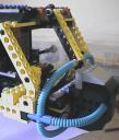
| | OK. Here’s the cockpit close-up with my attempt at life-like shaping. It’s not fantastic, but I’m definitely a functionality type of guy, so don’t usually spend much time on looks. The second shot shows how I got the 3 flex tubes arranged as shown (not really trick - I just wanted to document it).
|
Main rotor control (swash-plate)
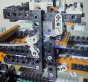
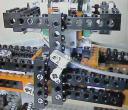
| | Here’s 2 views of the swash-plate from opposite sides of the helicopter. This text is where the rear of the helicopter would be in both shots. Explaining how the motion controls the rotor is confusing, because left/right motion of the swash-plate causes the ‘copter to tilt forward/backward. This is because the linkages to the rotor blades are 90 degrees out of phase with the blade they control. This also means that forward/backward movement of the joystick produces left/right movement of the swash-plate
On the right you can see the flex cable that tilts the whole mechanism forward & back. This is driven by left/right movement of the joystick (see above). On the left is the cable producing left/right tilt. Note that only the turntable tilts left/right (you can just see it in these shots). You can also see how the correct relative movement is produced - when you push the joystick (e.g.) left, both flex cables move an equal amount. Because the left/right cable (left photo) is anchored to the vertical control, the 3x1 link it controls moves the same distance as the whole mechanism, so it doesn’t move relative to the forward/backward tilt. I haven’t explained this very well, so you may have to take my word for it.
Note also that the whole mechanism moves up & down, controlled by the collective.
| | 
|
More details
| | 
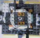
| | These shots show how the turntable is tilted. At the top left of the left shot is the linkage driven by the flex cable. It’s transmitted through 90 degrees using 2 bevel gears (old-style again!), then the right shot shows the actual linkage (as viewed from the rear of the helicopter). The turntable is attached using 2 2x1 beams with cross-hole. It had to be done like this, so the linkages to the rotor blades could be attached as close as possible (in height) to the point from which the swash-plate tilted. This minimised lateral movement of said linkages. (The brick separators are purely for display purposes!)
|
Main rotor details

| | 
| | Details of the main rotor itself. On the left is a view with the complete swash-plate / main rotor assembly - it looks a bit strange because both left/right and forward/backward controls are at their limits. You can see the rotor shaft emerging through the swash-plate, and the rotor blades themselves, shortened for display purposes. The right photo shows the detail of the head of the main rotor - the control linkages are connected to the 3/4 connectors. I was a bit worried that the weight of the blades would put undue stress on the #8 axles, and either bend them or loosen the bushes, but they were fine when I dismantled it. Each blade was 56 studs long, and 2 studs by 2/3 brick thick.
|
Drive chain

| | 
| | The one-way clutch. Fairly simple in operation, when the motor turns clockwise, the clutch dis-engages. The weight of the 16 tooth gear is enough to re-engage it when it turns anti-clockwise. But the main reason for it is so that the rotor can continue turning freely after the motor is switched off. This avoids the main rotor assembly being damaged due to its own inertia.
Here you can also see the vertical shaft which drives the main rotor shaft via a chain (see below).
|
Gearbox & chain drive
| | 
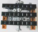
| | On the left is the gearbox. The input (top) also drives the tail rotor via a long series of shafts connected by universal joints. The output drives the vertical shaft (above) via 2 bevel gears (new-style here for strength). The main rotor shaft is driven from this via a chain (apologies for picture quality!). I did it like this to get maximum cabin space. I’ve included an earlier side-on shot to show how much cargo space is available.
| | 
|
Tail section

| | 
| | This shows 2 extreme views of the anti-torque assembly at the tail rotor (from above). The linkage from the pedals basically moves the small turntable along the rotor shaft, and the connecting rods “twist” the rotor blades (absent in these pictures) in unison. If you read the construction notes, you’ll know I originally did it without the turntable, using rubber bands, but this put way too much resistance on the shaft when the rubber bands were stretched. It also meant the pedals were pushed in one direction - not fun for the pilot!
|
More details

| | 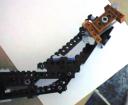
| | Left is the tail rotor from underneath, showing the shaft drive. Note I did the angle with 2 universal joints, to get as close as possible to constant velocity. On an angle such as this, universal joints are nowhere near CV - the output speeds up & slows down twice per revolution for a constant input. Putting 2 in series means the centre shaft turns un-evenly, but output is fairly constant, if the two angles are about the same.
Right is a profile of the end of the tail section. I tried to get it as “life-like” as I could. You’ll have to imagine the rotor blades...
|
Miscellaneous
| | 
| | 
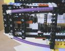
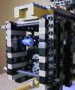
| | I’ve put these here ‘cos they didn’t really fit anywhere else. Left is the rear of the cabin, showing my attempt at “life-like”.
In the middle is a close-up of the reinforcing required to make the tail section detachable. OK, it’s probably over-kill, but I wanted to make sure. The tail section was relatively long & fairly heavy, requiring a very strong joint here. It’s held in place by the 2 #12 axles. You can also see the shaft emerging from the gearbox, to which the drive for the tail rotor is attached via a universal joint, and the blue pin/bush used to connect the anti-torque linkage to the tail. Both these had to be easily dis-connectable, in order to detach the tail section.
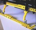
Also, detail of the skids. No rocket science here, but the thing was quite heavy (I didn’t actually weigh it. Anyone wanna guess?) so they needed to be strong but not too bulky.
|
|
 |
Site last modified November 4, 2004 Home
|
